Power Management Controller

Reliable power management for critical infrastructure

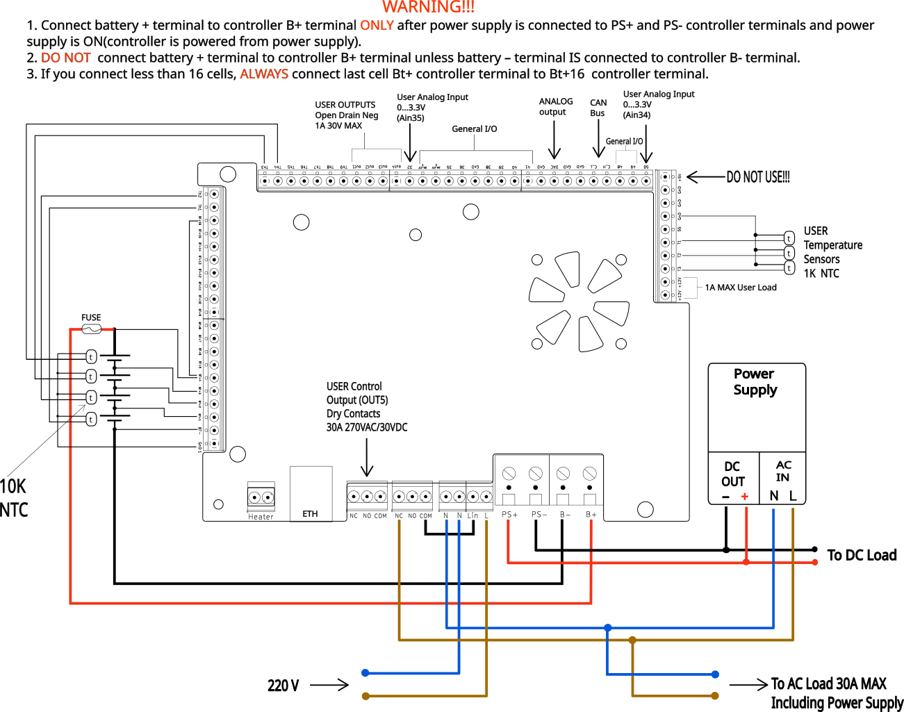
MC-30 is an intelligent controller designed to provide uninterrupted power for telecom nodes, including OLT, aggregation, and transport equipment. It monitors AC and DC parameters, automatically switches power to batteries, manages charging and balancing, and supports heating and cooling, while also providing full telemetry and remote alerts.

10–75 В DCOperating voltage range
30 АMaximum charge current
45 АMaximum discharge current
185×140×45 ммDevice dimensions
MC-30 power supply controller MC-30 connection diagram MC-30 product package image image
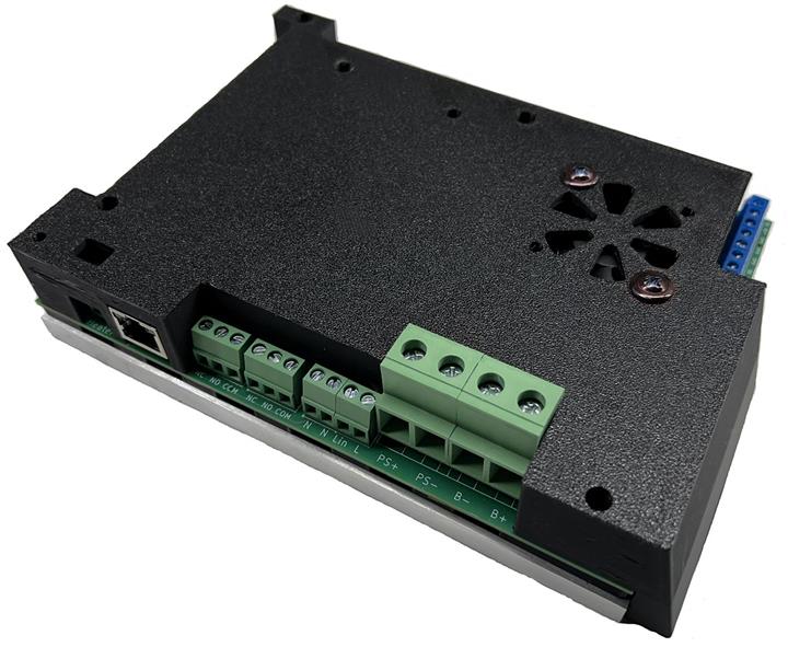
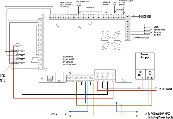
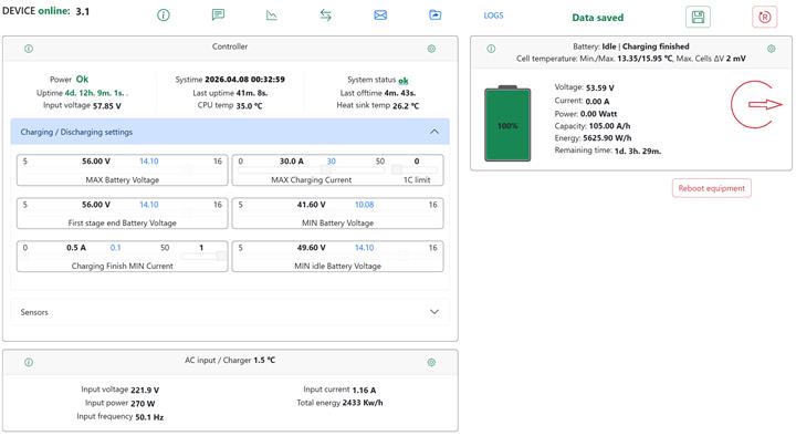
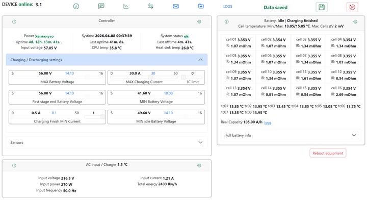
MC-30 Power Controller

Purpose

A managed controller for uninterrupted node power supply that combines power source monitoring, battery management, temperature supervision, control of external devices, and remote access in one solution.

Core functionality

  • Continuous power supply for telecom nodes: OLT, aggregation, and transport.
  • Monitoring AC and DC voltage in real time.
  • Automatic switching to batteries and back based on configured thresholds and timing.
  • Control of external actuators and devices.
  • Full telemetry and alerting capabilities.

Supported batteries and configurations

  • Chemistries: Li-ion, LiFePO₄, and lead-acid batteries.
  • Lithium configurations: from 3S to 16S.
  • Lead-acid: up to 4 × 12V batteries in series.
  • Stack voltage range: 10–70V.
  • Active and passive balancing of cells and batteries.

Monitoring and Analytics

The controller continuously collects power, battery, and environmental data to ensure stable node operation.

01

AC monitoring

Continuous measurement of voltage, current, power, and frequency, with detection of sags and overvoltage events and AC energy metering.

02

Switching logic

Automatic AC → battery switching and return, with debounce logic, delays, and hysteresis for unstable power grids.

03

Temperature control

Monitoring of battery cell temperature, room or enclosure temperature, as well as heating and cooling control.

04

Battery analytics

Current, voltage, capacity and energy in Ah/Wh, SoC, SoH, internal resistance, and battery imbalance.

05

Runtime estimation

Calculation of remaining battery runtime under current load for better service planning.

06

Per-cell analytics

Per-cell temperature monitoring and parameter measurement for more accurate battery condition management.

Battery charging and protection

  • Managed battery charging.
  • Adjustable current limit up to 30A.
  • Dedicated voltage/current/condition profiles for different chemistries.
  • Temperature-based limits when required.
  • Protection against undervoltage and overvoltage both per cell and across the stack.
  • Protection against overcurrent, temperature limit violations, and low-voltage cutoff.

Configurable parameters

  • AC voltage thresholds.
  • Balancing thresholds.
  • Internal resistance measurement and equalization intervals.
  • Battery heating thresholds.
  • Charge current limits and charging profiles.
  • Network parameters, access settings, users, and policies.

Alerts, events and service

MC-30 is designed for remote maintenance, fast response, and centralized control of distributed nodes.

Alerts and events

  • Threshold alerts when SoC or remaining energy drops below the configured level.
  • Monitoring of voltage, current, and temperature excursions beyond permitted limits.
  • Detection of AC loss/restoration and power source switching events.
  • Alerts about abnormality and system errors.
  • Custom rules and user-defined alert conditions.

Remote operations

  • Remote restore — remote recovery or restart of node power.
  • Online remote configuration of key parameters.
  • Extensibility and updatability to meet customer requirements.
  • Local indication and notification delivery through network channels.

Interfaces and Integrity

Ready for integration into modern telemetry, control, and external device management systems.

Communications

  • Ethernet interface — wired connectivity for control, telemetry, and alerts.
  • Wi‑Fi interface — wireless access.
  • Web interface for configuration.
  • API for integration with external systems.

Inputs and outputs

  • Analog inputs for custom use.
  • Digital inputs for custom use.
  • Temperature sensor inputs.
  • Outputs for external control.
  • Control of alternative power sources, ATS, or relays.
Ethernet Wi‑Fi WEB-interface API Analog Inputs Digital Inputs Temperature Sensors ATS / Relay Control

Connection Diagram

This wiring diagram shows the typical MC-30 connection layout, including the power supply, battery stack, AC load path, temperature sensors, user I/O, and auxiliary control connections.

MC-30 connection diagram

Important: follow the connection order and terminal labeling shown in the diagram to avoid incorrect wiring or controller damage.

Electrical and operational data

Key device parameters for a quick overview.

Number of cells3–16S
Number of lead-acid batteries1–4 pcs
Maximum charging current30 А
Allowed AC voltage0-300 В
Allowed DC voltage range10–75 В
Maximum discharge current45 А
Maximum AC current24 А
Dimensions W×L×H185 × 140 × 45 мм